October 18, 2018
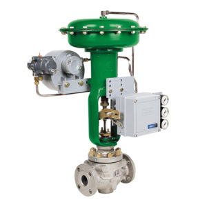
 So, you’ve just received your remanufactured Fisher® DVC6000 controller. What’s next?
The first thing you need to do is calibrate the device following the instructions below. If you have any questions or run into any problems, call (800) 325-4808 to speak with one of our product technicians.
Click here to download a one-page, easily printable version of these instructions.
Steps to Calibrate a DVC6000 Controller
On receiving a DVC6000 the instrument mode is “In Service.” Follow these simple steps to get your device up and running.
- This Mode needs to be changed to “Out of Service” during configuration
- Communicator Path: Setup and Diag/Detailed Setup/Instrument Mode
- Take out of service
- Next step is to teach positioner the equipment it is working with
- Communicator Path: Setup and Diag/Basic Setup/Setup Wizard
- Upon selecting you will be prompted by communicator to input several pieces of information: MFG, Actuator Type & Size, Supply Pressure, etc.
- It will prompt for factory default – choose YES.
- After info is entered communicator will prompt you to enter Travel Calibration
- Will ask Auto- or Manual- control – Auto is suggested
- After choosing Auto it will ask you for Crossover Adjustment Source to define the midpoint – select Manual.
- During Auto Calibration valve will open fully and close multiple times while searching for its end points.
- You will be asked to define a midpoint (crossover) – Adjust input current as needed (near 12 mA) until feedback arm is perpendicular to the adjustment arm.
- Select “Continue” with Auto Travel Calibration.
- Once Auto Travel Calibration is complete
- Communicator will prompt you to put back in service – choose “In Service”.
- Adjust current source from 4-20 mA and note valve position.
- Linear? Verify functionality.
- Non-linear? Needs further adjustment.
- If DVC fails Auto Travel Calibration:
- Check travel sensor adjustment – see related section of manual.
- Verify I/P functioning properly – is I/P Linear?
- Verify pressures on output pressure and supply gauges.
- If DVC passes Auto Travel Calibration, but is unsteady or oscillates:
- Adjust response control – dampening.
- Communicator Path: Setup and Diag/Detailed Setup/Response Control/Tuning Set
- A letter was assigned during setup to factory default – choose a lower letter – move a couple steps lower at a time, may need to repeat until control smooths out.
NOTE: Different device descriptions and DVC styles may have slightly different terminology. Path give is based on 375 or 475 communicator structure.
For more information about your new DVC6000 controller, explore these resources: