As featured in Flow Control® Magazine’s April E-Newsletter, Website and May 2015 Print Issue
 Often when commissioning or troubleshooting automatic control valves, there’s a discovery that the control valve, even though fully closed, doesn’t fully shut off the flow of process fluid through the plug and seat. Although closed, there is an “allowable leakage rate” as part of each control valve’s specification. The following article aims to clear up some confusion about the shutoff capability of control valves.
An automatic control valve opens and closes to increase or decrease the flow of process fluid through it to keep a measured process variable at its desired setting. While these types of valves are very important and perform the job of controlling a process very well, they don’t always close tightly enough to completely shut off the flow of process. Nor should they be expected to.![]()
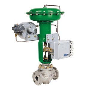
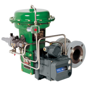
The components in a control valve that modulate the flow are called “the trim”. There are different types of control valves and different types have different components that serve the purpose of “trim”. For instance, in a sliding stem globe valve the trim is made up of a plug and stem, a seat ring, and usually some type of plug guiding or flow characterizing device called a cage. In a V-notch, segmented ball valve the trim is made up of a ball and shaft, and a seal ring or seat ring. In a butterfly valve it’s the disc and seal ring. These trim components are designed to best throttle the flow as smoothly and efficiently as needed. Asking these same components to completely and effectively shut off the flow of process fluid can often be a challenge, since that’s not what they were designed to do.

Although some manufacturers of automatic control valves will claim a “tight shut off”, on some of their valves it requires special parts, materials, and manufacturing assembly. The American National Standards Institute (ANSI) recognizes and classifies a range of acceptable seat leakage allowed in a control valve, see Table 1. That’s right; the American National Standards Institute acknowledges “a maximum allowable seat leak rate” for given requirements. Furthermore, there’s the American Petroleum Institute (API) Standard 553 for Refinery Control Valves that references the ANSI/FCI Standard for allowable leakage.
But, if the control valve is closed, should it not leak? I’ve had a mantra of sorts for years that goes like this; “Control valves control, shut off valves shut off. And neither one does the other’s job very well.”
If the idea of a control valve is to modulate and throttle the flow of process fluid, then in most applications the process is always flowing, more flow or less flow depending on the process control loop’s demands. So if the flow is always flowing, why the concern to completely shut off the flow when closed? Some applications may require a certain level of tightness of closure, with the control valve being closed at frequencies and durations often or long enough to effectively control the loads changes that happen in some process applications. If a control application requires a tighter than ANSI standard shut off, there are options with the control valve trim that may be able to provide an optional tighter shutoff. These options can include different seat materials, radiused contours to the seating surface of either the seat ring or plug, or additional seat loading from the actuator.
Let’s talk about the optional trim materials. A standard metal plug on metal seat can, and should give the valve a tightness of closure that meets the ANSI/FCI 70-2 Standard for a Class IV shut off. While a metal plug on a seat with soft, resilient material such as PTFE, EPDM, or other elastomer can provide as high as a Class VI shut off. Another option that can be used is a radiused contour on the seat ring seating surface (standard being a beveled seat) that can provide a more efficient single point of contact between the plug and the seat ring. Tighter shutoff can also be achieved by greater seat loading, where the actuator delivers a higher amount of thrust, resulting in greater force in pressing the plug against the seat. So after these steps have been taken to provide a “tighter shutoff”, the valve may still not achieve complete positive shutoff. Then a “companion” shut off valve inline with the control valve may also be needed. But before we go “there”, consider the amount of “allowable” leakage, that leak rate can be extremely small. For example, a 2” full ported globe-style control valve with metal seat and plug that has a rated full capacity of 100 gallons per minute of flow is only allowed, at Class IV Shutoff rates, to “leak” a maximum of 0.01 gpm, or less than 8 Tablespoons per minute. Another example of a 6” V-Notch Ball Valve with soft seal and a rated full capacity of 9500 gallons per minute is allowed a Class VI maximum leakage rate of 0.001 gpm, or less than a teaspoon per minute. Seems rather insignificant in that context. And in practice, many tests performed on control valves show most valves far exceed their rated shutoff tightness, some being “bubble tight”, or zero leakage, not even allowing a bubble of test medium gas to pass through the valve.
In most automatic control valve applications, the allowable leakage rate will be more than sufficient shut off capability. And if you need more, consider a higher shutoff classification, or using a companion shut-off valve.
| Leakage Class | Maximum Seat Leakage | Test Procedure |
|---|---|---|
| Class I | See Para. 4.2.1 of ANSI/FCI 70-2 | No test required provided user and supplier so agree |
| Class II | 0.5% of rated valve capacity | Type A (See Para. 5.1 of ANSI/FCI 70-2); pressure applied to the valve inlet, with outlet open to atmosphere or connected to low head loss measuring device, full normal closing force provide by the actuator. |
| Class III | 0.1% of rated valve capacity | Type A (See Para. 5.1) ); pressure applied to the valve inlet, with outlet open to atmosphere or connected to low head loss measuring device, full normal closing force provide by the actuator. |
| Class IV | 0.01% of rated valve capacity | Type A (See Para. 5.1) ); pressure applied to the valve inlet, with outlet open to atmosphere or connected to low head loss measuring device, full normal closing force provide by the actuator |
| Class V | 5 x 10⁻⁴ ml per minute of water per inch of seat diameter per psi differential | Type B (See Para. 5.2) |
| 5 x 10-12 m3 per second of water per mm of seat diameter per bar differential | Type B (See Para.5.2) | |
| 4.7 standard ml per minute of air per inch of orifice diameter | Type B1 (See Para. 5.3) | |
| 11.1 x 10⁻⁶ standard m3 per hour of air per mm of orifice diameter | Type B1 (See Para. 5.3) | |
| Class VI | Leakage per Paragraph 5.4.4 as expressed in ml per minute versus seat diameter | Type C (See Para. 5.4) |
Browse our Ultimate Cheat Sheet on Fisher® Control Valves to learn more about remanufactured control valves.
Jerry Butz, BSEE, CMRP, joined Automation Service in 2010 and serves as the company’s Director of Customer Engineering. Before this, he worked at DuPont for 16 years. Butz also has a background in electrical, instrument and reliability engineering, as well as construction, commissioning/startups, predictive/preventive maintenance, troubleshooting, root cause failure analysis and process control engineering. He has 29 years of field experience in the petrochemical, biofuels, and extrusion/web handling industries. Butz received his B.S. in electrical/electronic engineering from Hamilton Technical College, is a Certified Maintenance & Reliability Professional, and is ANSI registered and Six Sigma certified. Contact Jerry directly at jerry.butz@automationservice.com.
View Original Post on Flow Control website
Also Read: Validating Remanufactured Control Valves
About Automation Service
Automation Service supplies Remanufactured Fisher® control valves and actuators as well as other Remanufactured Fisher and Remanufactured Rosemount® products to industries such as pulp & paper, chemical, petroleum, utility, water & wastewater among others. Every Remanufactured Fisher valve assembly and Remanufactured Rosemount control is built precisely to customer specifications and thoroughly tested for safety, reliability and efficiency. All Remanufactured Fisher and Remanufactured Rosemount products are covered by a 2-year service warranty that starts from the date of installation.